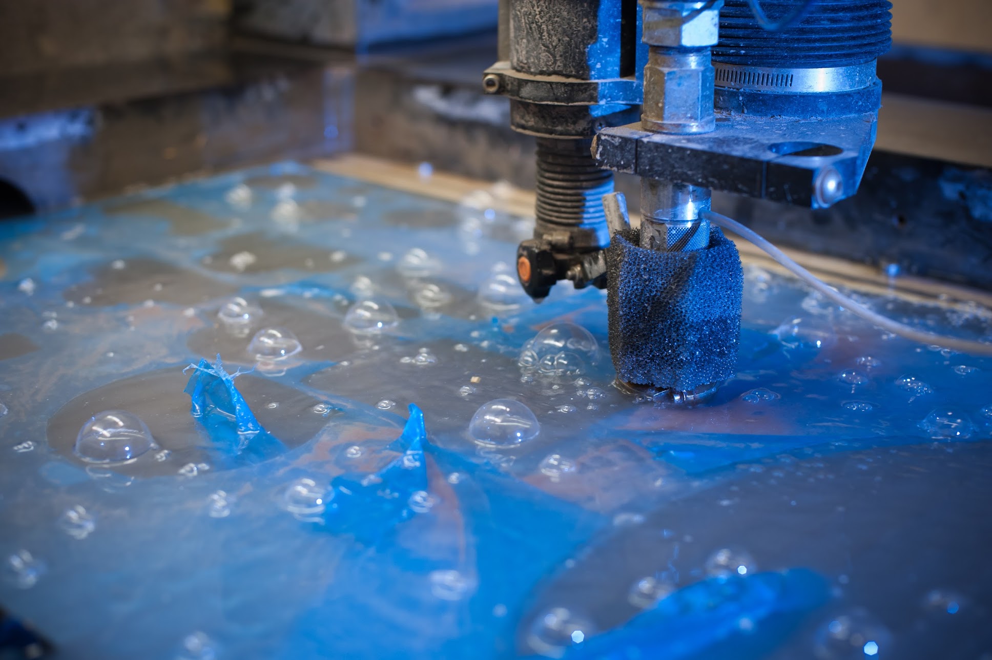
WATER-JET CUTTING
Water-jet cutting is heavily used for many industrial applications because of its ability to precisely cut through materials. It is best suited for cutting shapes and designs out of 2D materials (i.e.- a sheet of metal and plastic).
OMAX 2652, 2 dimensional, 2’ x 4’ or 609.6 mm x 1219.2 mm
Because the water-jet has some physical constraints when it comes to its programming and construction, it is important to consider these in the process of designing.
Sharp-edges
90 degree sharp angles cannot be made precisely with the water-jet. When a 90 degree angle cut is required from the water-jet cutter, it will create some funny cuts that can be off from your design. However, if you add a bit of a curvature to these sharp angles. It will be helpful for you to take the sharp angle into perspective and include a small curvature as shown in the picture below.
Concave vs Convex cuts
When it comes to cutting things involve cutting an object that has a sharp edge such as the motor rotor shown in the picture below, it's important to take into consideration of how the machine cuts. For an object of which you would like the object to be sharp, consider the fact that there will be a deviation from the actual design/ product.
For more advice on cutting, please contact Matthew Kutarna.
Here is a video made by Professor Gelbart on some Water-jet basics:
1. Open the part file and close any assemblies that the part is included in.
2. Flatten the part.
3. Click "Save As", select "DXF", and save the file.
1. Waterjet Parts (Standard): Generate Files
2. Open the part file and close any assemblies that the part is included in.
3. Determine which view (top, front, side) shows the shape you want to be cut.
4. Click "Save As", select "DXF", and save the file.
5. You will be prompted for a "View to Export". Select the view from step 2.
Project Courses Undergrads, refer to course support. Grads can send directly inquires to shop@ece.ubc.ca.
Is recommendable provide Mechanical Drawings in PDF to avoid any confusion.
MILLING
Milling is the process of refining surfaces and cutting down surfaces.
HAAS VF1 Milling Machine – 3 dimensional, Z-axis is dependant on tool length, X-axis is 20” or 508 mm; Y axis is 16” or 406 4 mm
For a page of basic Milling examples and knowledge please visit HERE or by watching this video: This service is available for students and faculty in the department. For more information, please contact the machinist directly.
TURNING
Turning is the process of cutting a piece of material by having it rotate as a non-rotating tool cuts it from the side.
For a page of basic Turning examples and knowledge please click HERE or visit this video:
This service is available for students and faculty in the department. For more information, please contact the machinist directly.
WELDING
Welding is the process of fusing together metal and thermoplastics using heat. Our machinist holds a certification that allows them to preform welding for projects at ECE.
For more information about welding, please CLICK HERE
This service is available for students and faculty in the department. For more information, please contact the machinist directly by email or in person.